Basic Structural Engineering
This section explains the forces that building components are put under as well as how the materials are use to resist those forces. Essentially this is about keeping the building standing up, not only under its own weight, but that of the stuff in it, snow on the roof, earthquakes, wind and even a room full of people dancing. Understanding this section is not critical for green building at all, but it will help with understanding the structural implications of both design decisions and wall/roof choices.
Actual structural engineering involves calculations to determine sizes. This section is only about principles, with the calculations left to the engineers.
Forces
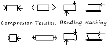
There are four kinds of forces that affect the structure of a building: (1) compression is the force trying to squeeze something, and is generally, but not always, a downward force (2) tension, which is the force pulling something apart (3) bending, which is trying to bend the material, and (4) lateral (or racking) which is a force applied unevenly to a wall which wants to twist it out of shape. The diagram at right shows the four forces: the arrows indicate the direction of the force. The top row is the initial state of the material and the bottom row is what happens when the force is applied, although the movement is exaggerated: in reality most building materials will only change shape a small amount before they break.
Compression: this force is usually due to the weight of something sitting on it, for example the weight of the roof on the walls below it. That why walls that carry that weight are called load bearing, in that they carry the load (weight) of everything above them. The force from below is not the kind of you think of when you push something, but it is still effectively as if the ground is pushing back. If the ground is weaker than the thing above it, the ground will give. In this case some part of the building sinks (think leaning tower of Pisa, but many old houses in the US have sloping floors because some part sunk).
In a compressive load, something is being squeezed. Materials are often very much stronger in compression than in other ways, so when they fail (break) its usually not a compressive failure. In fact most loads are not strictly compressive: in the diagram above the forces are shown as being perfectly straight, but in reality that is not usually the case-- at least some part of the force isn't straight down.
If you put 24" piece of 2x4 flat on solid ground and stand on its ie you are 1-1/2" off the ground), its a purely compressive load because the flat 2x4 can move any other way. However if you now stand that 2x4 on end (ie you're now 24" off the ground) and try to stand on it the first thing you find how difficult this is because balancing your weight on the center is hard. Assuming you do manage to balance on it with sufficient weight, it won't fail by compression, but instead will bend and break. The fact that this is the case is more obvious if you think about standing on the tip of a 8' 2x4: the ratio between compressive strength and bending strength is shifted, and clearly the 8' 2x4 will bend and break long before you crush it.
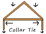
Tension: the most obvious place that tension occurs in a house is when there is a pitched (ie not flat) roof. In this case the weight of the roof pushes outward on the walls. This is just like when you built a house out of playing cards or for that matter tilt one book up against another like a roof: they collapse by falling flat, ie they don't bend or break; they fall down. To combat that in buildings we generally tie the bottom of the two sides of the roof together so that they form a triangle. This bottom piece, which is referred to as a collar tie1 is then in tension: as the two parts of the roof want to fall down, they pull on it trying to make it longer. This outward force is the same whether the roof is a wood framed pitched roof or an arched roof on a cathedral.
In the diagram (above, right) the downward weight of the roof pushes down on the support walls, but also wants to push them apart. The collar tie holds that force in check so that all the weight ends up going down the support walls.
For a roof there is an alternative in that we can use a post to support the peak of the roof, and this eliminates the outward force, but requires posts running down the middle of the building. Tension also plays a role in every truss and system to prevent racking, which is described later.
Bending: a bending force is often due to weight, but unlike compression, the weight sits on a material that is not supported. So using our 2x4 example, if you take the 24" piece of 2x4 and set it up on blocks then stand in the middle, the 2x4 will want to bend in the middle. While the 2x4 supported flat on the ground won't crush until you put many thousands of pounds of weight on it, the unsupported 2x4 will bend and break under a much smaller weight. There is a further complication here in that the bending strength depends on the unsupported length of the material as well as the material itself and in all case the longer the unsupported stand, the lower the bending strength is.
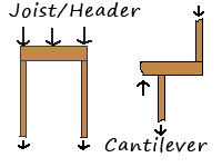
Bending forces occur all over in buildings. Floor joists and roof rafters both experience bending forces because there is weight on them, and nothing underneath them. The area above windows and doors is also a bending load: in this case, the load of the wall above the middle of the window rather than pressing on the window is made to press on a header, and the header is designed stiff enough so that rather than actually bending it transmits the weigh to posts on the sides of the window as a compressive load. Again, because materials generally have a lower bending strength than compressive strength, the header is much bigger than the posts that carry its load to the ground. In the joist/header case in the diagram at right, both situations present a load over an unsupported area.
From the bending perspective, floor joints, window headers and cantilevers are all the same. The cantilever case is more interesting, because there is a bending load on the joist, but because there is support columns on only one side, the bending load does not get simply converted to a compressive load on the close column. In the simple case (indicated by the upward arrow), the joist wants to act like a see-saw where as long as the joist doesn't bend, the cantilevered wall want to lift the opposite wall off the ground the same way someone on one side of a see-saw lifts the other.
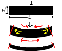
Strength in bending is not just a property of the material, but the thickness of that material that is being bent. To understand this you need to see where the strength in bending comes from. In the upper image at right is an imaginary beam supported on both ends and with a heavy force in the middle trying to bend it. The key is looking at what happens at the shape of the beam as it bends. Because both the top and bottom are the same length, they must stay the same length or break, and so the shape they would take on when bent is shown in the middle example. If you take a large stack of paper (100 sheets or so), and hold it on the edges it will droop into the exact shape of the middle picture. So why doesn't a solid beam do this? Now start off using something else to support the middle of the stack of paper, then slowly remove that support and let the stack of paper droop: an interesting thing happens: the sheets of paper slide across each other (indicated by the yellow arrows), the the topmost sheet sliding the most and the lower sheets sliding less with the bottom sheet effectively remaining fixed2. What happened here is that the stack of paper distorted in a way a solid beam cannot. In fact the shape of the beam at the ends can't be as indicated by the black area, but must be cut off at the red lines: our original shape was rectangular, so unless the material changes shape internally as the stack of paper does, the corners at the ends must still be each 90° but this itself is an impossible situation as now the upper side of the beam is shorter than the lower side. In fact this is exactly what is essentially going on--the upper part of the beam is in compression, and the lower part is in tension (indicated by the red arrows). At the top of the beam, the red arrows are in the opposite direction as the yellow ones: that's because the yellow arrows are the direction the beam wants to stretch to relieve the stress, while the red arrows are the direction of the stress.
Since the beam is one solid piece of material it will tolerate on a very small amount of compaction due to compression and stretching due to tension, and so would never actually bend the amount shown in the middle diagram, but rather it will break first, splitting open on the tension side somewhere.
In the bottom example in the above diagram is a beam that is much less wide, and so when bent the difference between the shape it wants to be and the shape it must be is much smaller, and that is why this shorter beam will not resist bending as much as the taller one.
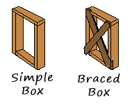
Racking/lateral loads: if you build a box, say out of 24" 2x4s again so now you have a 24" x 24" box, but back or front. Now stand the box on end and stand on it. If you're careful and stand still, nothing will happen, but if you wiggle back and forth, likely your box will collapse in a similar way to the way a roof collapses. It will collapse by pulling, bending or otherwise destroying whatever fastener you've used (nails, screws, glue) leaving the four pieces of 2x4 largely intact (that is assuming the whole thing doesn't just fall over the other way, which is a different problem). This is a racking load (or sometimes called lateral because its generally its a left-right load, not up down). The 'racking' case in the diagram at the top of this page shows this lateral load being applies to a box anchored to the ground, and the resulting distortion that happens when its not braced.
The simplest solution is to put a 24"x24" piece of plywood on one side of your box, and its now immensely stronger: wiggle all you want and your box will no longer collapse. To understand why, replace the plywood with two small pieces of wood connected in the corners in an X. Now when a racking force is on the box, the cross braces prevent it from moving, because the geometry of the situation is that the racking movement converts a square into a rhombus, or a rectangle into a parallelogram. In both the rhombus and the parallelogram, the diagonal distances aren't the same: one gets shorter and one longer. So the X shaped cross bracing prevents this because as the box starts to distort, the diagonal that wants to get longer puts the cross brace in tension while the getting shorter goes into compression.
Special Structural Forms
Arches: an arch is essentially a pitched roof but with a curve in it, so that any bending load is convert to a compressive load plus and lateral (outward) load. The arch allow you to build a roof out of materials like stone that have high compressive strength, but not much bending strength, but once you put the arch on columns, the outward force wants to topple them over. You could use collar ties, and you could also put a band around the outside of the building: both would work in tension to fight the outward force. Medieval builders didn't have those options, so they resorted to using only other compressive loads to counter the outward force.
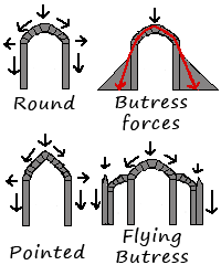
In the diagrams at right, each arch has a presumed load from above: that load moves incrementally thru the blocks of the arch into a combination of downward and outward forces. The diagonal arrows show the direction of the force thru the arch, while the outward and downward arrows indicate that both those forces exist on the column below the arch. The red arrows show the force being transmitted thru the columns as well. In this case, because the red arrow falls outside the arch, the arch will fall down without any additional support. In this diagram, the gray triangles are theoretical buttresses that resist the outward force. As it turns out the buttress doesn't need to be this wide, especially if its a bit taller than the arch and very heavy. In this case, the sheer weight of the buttress has enough friction in it to resist the outward force. To see how this makes sense, imagine stacking 12"x12"x12" square stone blocks on top of each other. At about 6 blocks high, you can probably push them over. Now make them 24" x 24" x 12" high. These blocks weigh four times as much and now it is unlikely you can push them over because they are just too heavy (and the friction surface is 4x greater also. If you want to support a tall main arch, another way to do it is with a smaller side arch, which itself is braced by a buttress and pinnacle. Pointed arches have lower lateral loads than rounded arches because they are taller, and hence the direction of the force is more downward than outward: the force follows the shape of the arch.
With the discovery of the truss and materials like steel with high tensile strength, arches are not generally used in buildings anymore. Arches in modern buildings are usually fake: they are typically lightweight decorative walls that hang from a beam with high bending strength. In houses, arches are usually made of two sheets plywood cut in the appropriate shape and held apart by little blocks of 2x4. The entire assembly is then covered in drywall or stucco.
For a great animation on how arches work, see this PBS arches animation.
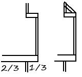
Cantilever: A cantilever is an structure that is unsupported on one end (see drawing under "bending" above). Roof eaves are often cantilevered as are bay windows. A cantilever is nothing other than a see-saw where the supported side is designed to be effectively much heavier than the unsupported one, so even adding weight to the unsupported side doesn't cause it to sag. A general rule of thumb for cantilevers is the 1/3-2/3 rule: however much sticks out, two times that length must be supported, but clearly what really matters is that there is a substantial weight on the other side. As an alternative to cantilevering, a structure can also be hung off a wall as shown in the right example. In this case, much of the weight of the cantilever is now taken by the upper cross brace, which hangs in tension. If this bracing is strong enough, the unsupported section is now hung off the wall rather than cantilevered. Needless to say it can be supported from underneath by a diagonal brace as well--the difference being that this brace would be in compression instead of tension. This same sequence of diagonal bracing alternating between compression and tension is what makes up trusses, our next topic.
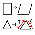
Trusses: a truss is structure made of pieces, each of which are triangles. There are two main kinds of trusses: flat (or parallel chord) trusses and roof (pitched) trusses. Variations on this theme are also used for bridges, ships, high power lines etc, but are not considered here. Triangles are strong due to geometry: while a rectangle can change shape to become a parallelogram without affecting the length of the sides, a triangle cannot change shape without changing the length of the sides. Any attempt to flex a triangle will result in one side being in compression and the adjacent side in tension. In the diagram at right, all four sides of the tall rectangle are the same length as when it is twisted. Trying to do the same thing to the triangle results in stretching the left side (hence its in tension), and compressing the right side.
The main advantage of trusses is that they use less material, or in particular they use smaller dimension material than their counterparts, other than that, a flat truss is no different than a beam, and a roof truss is no different from to corresponding rafter+collar tie configuration.
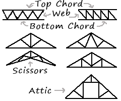
The parts of a truss are chords (top and bottom) and the web. In a pitched truss, there are two top chord pieces. The pieces of the web in a truss are always in opposition to each other, so if one is in tension, its neighbor is in compression. As with a beam, the top chord is always in compression and the bottom chord is always in tension. The triangles of the truss can be in a variety of configurations, each undoubtedly with its own advantages and disadvantages, but all work on the same general principles.
The diagram (above, right) shows two flat trusses and five pitched trusses. Three of the pitched trusses are just normal roof trusses but with different web configurations, and likewise the two flat trusses have different web configurations. The remaining two pitches trusses area the scissors truss and the attic truss. The scissors truss is used for vaulting ceilings and can be used as just part of a truss with the other part being a standard non-vaulted truss. The attic truss sacrifices some strength of the truss for a tunnel of usable space within the truss. Depending on the size of the useable space, attic trusses generally require larger dimension lumber for the top and bottom chords than do standard trusses.
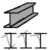
I-beams: an I-beam is really nothing but a flat truss with a solid web. In fact one can argue that a full size solid square beam is likewise similar to a truss. Like trusses, an I-beam is designed to do the same job with less material. The key here is that the strength of a beam is mostly due to the height of the beam (shown as H in the beam discussion above) not the width, so in fact you can reduce the width, at least along the center of the beam to quite small. This is equivalent to the web of a flat truss. In an I-beam the top and bottom are called flanges and they are equivalent to the chords on a truss. The flanges add little bending strength in the downward direction, but what they do is keep the beam from twisting. Because an I-beam with a small or no flanges has essentially no strength against twisting, when a bending load is applied, it hence is far more likely to fail that way than by actual bending. The flange adds strength against twisting, and also prevents bending in the other direction, ie side to side in addition to up and down. In the diagram above, the three bottom examples show the original I-beam in cross section (black) and various twists it can undergo (gray).
Steel I-beams are the most common form of I-beam, but are not that common in residential construction. Wooden I-joists are just I-beams made of wood. Because they're made of engineered (ie small glued pieces) wood, they are most stable than a solid wood beam and just as strong, so they tend to make for a stiffer, quieter floor (although partly this is due to the fact that most subfloors are glued down in addition to being nailed).
Notes
1: Technically you'd only call it a collar tie when it sits there by itself, not part of a truss or part of an attic floor. Regardless of how its built, that piece performs the same function, ie it provides the tensile strength to keep the roof from falling down and pushing the walls apart.
2: The stack also spans a somewhat shorter distance than the original length L because the length L is now a curved path rather than a straight one.
