Seattle - Energy
Envelope
In 2003 the standard for green building was 2x6 advanced frame walls filled with either BIBs fiberglass or cellulose, and simple calculations showed this wasn't really enough for Seattle's climate. We decided on double walls because its was the most obvious way to get more insulation given no one we knew had done it, although others had in other parts of the country.
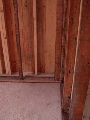
Double wall, Inner wall uses reclaimed studs
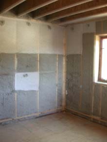
We chose 9" thick walls because the original house was brick and so it had a 9" thick wall and at the time we thought we were reusing most of the original foundation. On the recommendation of the energy consultants (Ecotope) we used cellulose instead of BIBs fiberglass on the theory that it would result in a slightly higher R-value, and add a small amount of air tightness. Whether any of that is true is unclear. What is true in retrospect is that cellulose adds significantly to the wall's ability to absorb moisture.
Both inner & outer walls are 24"o.c. and there is a 2" gap between them. Every 10' we used a piece of 1/2" ply across the studs vertically as a fire break, although no plywood was required to join the two top plates. Most of the windows have 1/2" ply all around, so the rough opening is framed 1" bigger in both dimensions so that its the right size after the ply is installed. This plywood could have been eliminated, although then netting would be required to hold in the insulation. The studs end up staggered in most places, which results in a slightly higher R-value, but they line up at windows and the difference in R-value isn't worth worrying about.
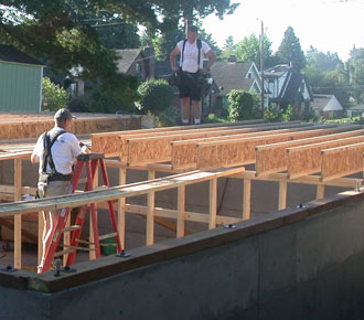
Had we gone the remodel route, the original floor was 2x8s, so we would have had about and R25 floor. Since we went the deconstruction route instead, we used 12" I-joists, which increased the R-value to about R40. Given that the basement is not as cold as outside, its not clear how much this improves the overall heat loss, but then the additional cost is minimal especially since the 12" I-joist were now there for structural reasons (or maybe just to ensure a stiffer floor, I'm not sure). In the photo you can see an I-joist laying on it's side and it's bending under its own weight--they're very strong the long way, but very weak in the other direction.
Originally we assumed we'd use either roof trusses or more 12" I-joist for the ceiling, but in either case, we assumed we'd put at least 12" of insulation up there. When the design ended up with a small dormer for Bob's 3rd floor office, we decided to try using an SIP roof, which meant that the entire attic space would be heated. Cost wise, this was a wash, but it increases the roof surface area and hence the heat loss thru it. However, the dormer room walls would then need insulation, so the total extra surface is not as big as it seems.
Given that there is a learning curve for installing SIPS, they probably could be installed for less cost than a standard stick frame roof if the crew was experienced in putting them in. Whether going with the SIPS was a good decision or not still isn't clear, but having heated storage space sure is nice.
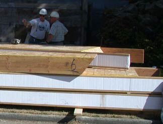
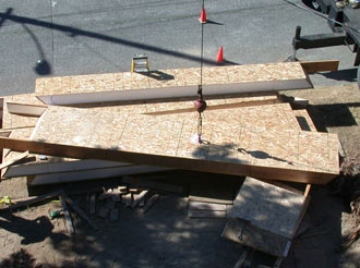
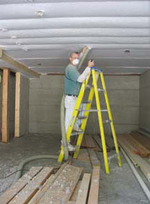
SIPs comes in 4' wide sections of whatever length it needed, and in this case are 12-3/4" thick: 12" of EPS foam and 2 layers of 7/16 OSB1. In our case the longest ones are around 21' and weight about 500lbs, so they are installed with a crane. When you see them on the ground the product doesn't look strong--its mostly foam, but in fact once installed its the stiffest roof I've ever walked on--it has no give at all.
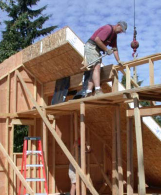
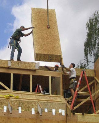
Each SIP slides into the other, although "slide" isn't a good term for it: you have to smack them pretty hard to get them to go together. In the upper right photo you can see the left side of the SIP has a slight depression in it: that depression fits the TGI in the already installed SIP. Before attaching them to each other, each joint is loaded with a lot of special (nasty) caulking. The SIPs are then attached at the top via 15" screws, and at the bottom there are additional metal plates (you can see them in the bottom of the right photo above). I think many of the metal plates were installed wrong--they were supposed to be slipped under a 2x4 plate, then nailed thru the plate and then bent up in an "L", and this bend will resist outward force much better than installing them flat, but I have no idea if this is true or not The two short ones were done right, the longer ones maybe were not. However, the SIPs are supported by load bearing walls near the peak and screwed in there, so there is probably plenty of redundancy there. In any case, the SIPS haven't slipped in ten years, so if there is a mistake its no big deal.
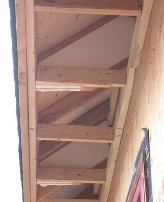
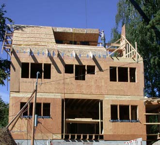
The SIP "rafter" tails are cut to the right angle, fascia installed, and a piece of plywood put on top to complete the roof. In this case, a soffit is also built (at right). Above is the nearly completed house.
In the "lessons learned" department, a downside of SIPs is that they're made to specs from plans, and if everything isn't specified quite right, the framer will still get it right, but the factory sure won't. In our case, there was a miscommunication about how the dormer framing interfaced with the SIP, with the net result being that the SIP roof on the dormer side came out and inch or so too long, which resulted in the framer peeling off the LVL end cap of the last SIP, shaving the foam, and then putting the end cap back in. It wasn't pretty, but it worked.
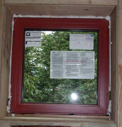
Our search for windows was frustrating. No US manufacture at the time made a window that was better than about U.28, so we ended up getting windows from Canada, where due to much larger heating loads high performing windows are more common. The difficulty is that they had no dealer in the area, so we had to work with them directly over the phone (the internet was also much more primitive at the time), although we managed to solve this by working with a local window dealer anyhow. Because the house is a sun-tempered passive solar design, the south windows need to have a high SHGC, which meant going with double pane windows, although we have the "northern" low-e put on them, so they're U.34, while the rest of the house got triple pane U.2 windows.
Doors were equally frustrating. The best you can find is R5, and so we went with that. Now there are door imported from Europe that perform better and at least one local manufacturer making a better one, but you also run into a hardware problem since all of these doors are more than 1-3/4" thick.
Air sealing
We used the spray foam on the interior of the sheathing method although we only sealed obvious holes, which at the time was all anyone did--in fact most builders did no sealing at all. The end result was 2.3ACH50, which at the time was considered very tight, but in retrospect it's only medium tight.
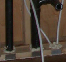
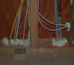
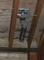
Sealing around ducts (left), pipes (middle) and wires (right). The duct itself is sealed with mastic.
We sealed all penetrations fairly carefully and we sealed around all the windows with non-expanding foam, and we also caulked the bottom plate to the subfloor. The place we didn't fully seal was the sheathing, where we only sealed the obvious gaps.
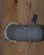
The heating ducts themselves are all sealed with mastic, and virtually all of them are in the heated space, although some run thru insulted floors
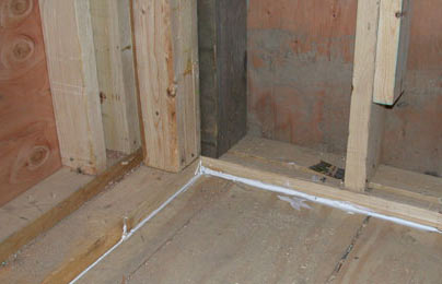
The bottom plate is caulked to
the subfloor (left). Non-expanding foam is used around windows.
There is no foam at the bottom of the window, because it sits tight on the
sill pan.
Insulation
Insulation choices are one of those choices where there is no ideal product. We ended up going with cellulose due to the usual reasons (recycled content, its somewhat of an air barrier, and although we didn't know it at the time, it stores quite a bit of seasonal moisture), but would say that working with it is not pleasant. If there is any obvious downside to cellulose, it is that it is terribly dusty, and the dust seemed noxious. The installers wore masks and as we were making last minute changes to framing and electrical, we quickly discovered that the dust is really irritating to your lungs and eyes. Even with a mask, you need to go to fresh air frequently to keep your eyes from getting too irritated. Like sheetrock, once installed, cellulose is best left alone. Of course it is easy to argue that fiberglass is just as bad, if not worse.
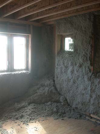
Damp spray in walls- in this case they're only 2x4 sound walls (left). But it frequently avalanched out (right).
The plan had been to use fabric on any ceilings, and damp spray the walls, but damp spray doesn't really work in deep walls--the insulation gets too heavy and it just avalanches out. Sometimes they were able to get it to stay, other times, they put some fabric up high and yet other times they put fabric on the whole wall. It would have been better if they just put fabric on the whole wall in the first place--you're more likely to get the correct density and hence no settling.
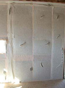
Blown in Cellulose: fabric on walls (left), damp spray with part fabric (middle), in ceiling (right)
There were two places we used a bit of polyiso instead of doing double walls--around the entire front of the ADU window bump out, and on the sides of the main unit window seat bump-outs. In both cases the framing is 2x6 with 3" of polyiso on the outside. I knew why they did this once, but I can't remember.
Passive Solar
South side on Aug 21st. Although two sets of windows have no
overhang, trees partially shade both of them.
The house was designed to be sun-tempered, which is a passive solar strategy that uses a limited amount of glass and no thermal mass. As it turns out, we put as much glass in as we were comfortable with, and we still couldn't get as much as we wanted. Part of the issue was the urban location where we weren't comfortable lowering the sills below three feet off the floor for privacy reasons. We otherwise filled the facade up so that both floors have almost a straight row of windows, but there are two foot gaps because architecturally that looked better and even if there weren't we ended up with a bathroom on the south side, so we had to reduce glass area for that, and had we not reduced the window area adjacent to the window seat bump-out we would have had side shading anyhow.
Seattle is a difficult solar climate in that there is almost no sun from around November 15th thru February 15th--in these months, Seattle only gets 10% of it's yearly sun. However in the spring and fall, Seattle gets about 50% of its sun, which combined with somewhat milder temperatures means that passive solar works quite well in these seasons even in cloudy Seattle.
We were a bit lax on making sure all windows had overhangs for architectural reasons, as you can see in the photo (above) two sets of windows have no overhang. However both sets of windows have some shading from trees, and because the temperature only occasionally goes above 80, and rarely goes above 90,combined with typical night temperatures in the 60s, we get away with this. Our overhangs are designed to totally shade the windows on June 21st, which means that we risk overheating for much of Sept. This is a problem that generally requires some kind of movable shade, but again because Seattle has a very moderate climate, in ten years there have been only a handful of days that movable shades would have been handy. In all cases, the warm days did not last long, and the house could be cooled at night.
Heating, Hot Water & Ventilation
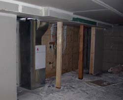
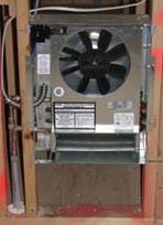
The heating system is a fan-coil driven off a hot water tank, which in this case is a Polaris sealed-combustion gas unit that can deliver 140Kbtu. The main unit is heated via a single air handler located in the basement (photo at left, below), and the ADU uses two wall mounted fan-coils. While it would have been nice to have the heating equipment on the main floor completely within the insulated envelope, at least we were able to find a central location in the basement, which kept the duct & hot water line runs reasonably short, although neither is as short as they could have been. It would have been more efficient to use fan-coils (or radiators) in the main unit as well, but fan-coils are a bit noisy and radiators take up wall space, so they were rejected.
We debated a bit about using in-floor heat, but thought that because you need to put ventilation in anyhow, and in-floor heat is typically more expensive, we'd go with the fan-coil. As it turns out, the air requirements for ventilation don't match well with the air requirement for heat. In the middle of winter we need essentially no ventilation air, but on average over 100CFM of heated air. As the days get milder, we need more ventilation air and less heat, so at that point our system theoretically would add fresh air to the cold air return. Because we're using the aircycler ventilation controller, when it gets really mild to the point that we need more ventilation air than heat, the controller runs the fan-coil fan, but without any hot water in the coils, and in addition supplies fresh air into the cold air return. At least that's how it was supposed to work. What actually happened is that the circuit board in the ventilation controller gave off enough heat to affect the thermostat to the point that the thermostat mostly wouldn't even turn the heat on. This happened because we mounted them on the wall next to each other and the vent in the ventilation controller happened to end up less than an inch away from the temperature sensor in the thermostat. The end result was that the ventilation controller got temporarily removed until the wire to it was lengthened, which involved cutting holes in drywall, and that's where the project still sits ten years later. We're careful to use our spot ventilation fans, and when the weather starts getting mild enough we open a window a crack and this seems fine. We get away with this because the house isn't really that tight (2.3ACH50).
Our ventilation system includes an HRV with a HEPA filter, which unfortunately uses quite a bit of energy due to the filtration (230 watts at full speed, approx 150w at low speed)--well it would use a lot of energy if it ever got turned on. Obviously using an HRV is better than using fans, but if the house is already fairly leaky using neither is even better. In retrospect it would have been better to make the house much tighter and actually use the HRV--although we would now specify a more efficient HRV and skip the filtration.
Connection for spot
ventilation fan
Our spot ventilation fans are almost all the Panasonic super-quiet, low energy ones--the exception is the kitchen fan because we needed a fan with a grease filter. Luckily Broan makes a reasonably quiet fan with a grease filter--its not nearly as quiet as the Panasonic, but its not bad. The Broan fan is a ceiling mount, not a range hood, and although it works well enough for us, it might not be good enough for a family that fries a lot. Its also 300CFM, so in a tighter house, the window would need to be opened a crack in order to run it.
The apartment has a Panasonic super-quite fan on a timer, which theoretically makes it run about 8 hrs a day. Unlike the main unit, we put in a duct for make up air into the apartment. It run from the roof down to behind the refrigerator and has a damper in it, so that unless there is negative pressure in the house (ie due to the fan) the damper doesn't open, and hence doesn't let any air in.
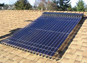
Our solar hot water collector
As with many fan-coil systems, the Polaris delivers hot water as well at heat, and the high BTU rating of the tank is so that it can deliver the full amount of heat to the house while also providing the full amount of hot water for the entire house (ie both units). Although the unit has broken multiple times (the igniter stops working--apparently this is a chronic problem with this unit). Since we have a solar hot water pre-heat tank, that is rarely below 60F, we probably don't need anywhere near the rated capacity of the unit, and in fact the unit seems to cycle (or at least the exhaust fan) frequently, which may explain the why the igniter goes out.
One annoying thing about this system is that is uses a thermostatic mixing valve (code required) to reduce the tank hot water (which is at least 140°F) down to 120. If that's all it did, things would be good, but it turns out it reduces the temperature of the hot water by 10F no matter what, apparently because the valve never quite shuts of the cold side. The result is that the tank has to be left at a minimum of 130F all summer even though we need no heat. If we had a better mixing valve, we could turn the temperature down.
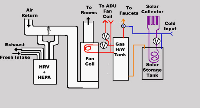
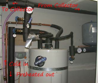
There is a solar preheat tank feeding the Polaris, which reduces the energy used for hot water. In the winter the pre-heat water is often around 60F (instead of 45-50F), and in the summer its often at 120F. The collector is a thermomax evacuated tube system with 20 tubes feeding a standard 50 gal HW tank (the heating element is not connected). The controller is set so that as long as the roof is at least 10F warmer than the tank, the pump runs--and thankfully this is a very efficient Taco pump (estimated to use about 25w). The photo at right shows much of the system (the pump is off the right hand side of the photo, next to the gray expansion tank, and the purple pipe is unrelated to the system).
Our plumbing system is PEX in a home-run configuration. Although the home-run configuration won't save energy for everyone, our pattern of use is quite random and so the smaller volume of water in the pipe means not only faster hot water, but less wasted energy. For a photo of the system, see the site-water section. We also tried as best to keep the plumbing lines in the heated space and when we couldn't we ran them as close to the heated space as code allows (ie we kept them in the inner wall).
Although fan-coil units avoid the "burnt dust" problem with forced air systems, the downside is that the air coming out of the ducts does not feel warm--presumably because it is usually below 100F when it comes out. Along with this the fan-coils heats the house very slowly: if the house has been vacant for a few days with the heat down, its takes many hours to heat it back up, although to be fair, a forced air system will heat the air in a house rapidly but it will also have to cycle frequently because the surfaces stay cold for hours, and hence cool off the air faster than normal. The other downside is that because air holds very little heat, you have to move a lot of air to heat a house, and moving that air takes a significant amount of energy. Its much more efficient to move a liquid. In order to deliver a reasonable amount of heat, the Polaris is set at 140°F instead of the normal 120°F, and when it gets very cold out, we have to turn the Polaris up to 160°F. This higher tank temperature means greater standby heat loss, which unfortunately is compounded by the utility closet being the worst insulated part of the house--of course because it got shoved in the basement and we didn't plan for a way to insulate it thoroughly.
Our ducts are almost all inside the heated space, and are all sealed with duct mastic. The big problem with ducts was that the basement is unheated and so either the duct ran in an insulated bay (reducing the insulation amount and leaving the duct only partially insulated) or the duct had to be run partly in a special drop down soffit, which meant the duct has almost no insulation. Luckily the basement is not that cold and the exposed runs are fairly short.
The heating system is all located in the basement for the same reason they often end up there--it was hard to leave space for it. It could have been in the attic, but that actually would have made all the plumbing runs somewhat longer (although it would have made the solar pre-heat run shorter)--plus then we would have needed a big drip pan in the attic and yet another drain line to outside. In retrospect we could have planned the basement closet better and then it could have been insulated nearly as well as the rest of the house.
If we had to do it again, we'd try to find budget for in-floor heat, and use one of the ventilation systems that work with 3" ducts. The other alternative would be to use a air-source heat pump and leave the ventilation system as is.
PV
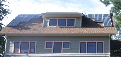
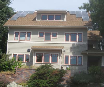
Although PV wasn't in our original budget, we prewired for it (3 wire #10, so you can send 220V, which allows up to 6kw). Budget and roof space dictated that the most we could put on is 3kw: there is shading from trees both east and west as well as shading from the dormer, which by itself shades enough space to put another 1kw on. The solar hot water system on top of the dormer also occupies some space, but its less than 1/2kw and we believe the HW collector collects more energy than the equivalent PV panels, but its hard to say if that's really true. Due to the shading problem we used a 3 part inverter (micro inverters weren't popular then) so that each of the three roof segments is independent of each other. As can be seen in the photo (above) taken in the afternoon, the tree on the west is shading the western part of the PV array, the part on dormer is probably going at full capacity, but the dormer is starting to shade the eastern segment. Unfortunately this tiny bit of shading will reduce that panel segments output by a disproportionate amount. We average about 2500kwh a year production, which is about 500kw smaller than it could produce, so shading is costing us about 17% of our potential production.
Lighting
We did nothing special for lighting during construction, using all normal Edison base fixtures, although we did minimize can fixtures, and installed only one ceiling room light per room. After we moved in, as it became clear what lamps were on often, we would change out the incandescent bulb for a CFL. Eventually we spend a week or so tracking approximately how many minutes each day each bulb was used and pumped them all into a spreadsheet. What became clear immediately was that at least half the bulbs were on so rarely that it made no sense to put a CFL in them, the savings is just too small. It turned out that only 11 bulbs were on for any length of time, and 4 of them were can lights on a dimmer, so we converted the 7 remaining ones to CFLs (and actually a few more borderline cases that turned out not to be worth it). Now that there are dimmable LEDs we can replace the final 4 incandescents, although since they're can lights we're waiting to see what the longevity of the bulbs are in that situation.
Because we have no control over the apartment, we suspect that the electric use due to lighting there is much larger, but unless we install one of the devices that can track that, we have no idea.
Appliances
It was amazing hard to find the most efficient appliances, and for the most part the sales staff had no clue. At the time, energy-star listed the energy use of each appliance, so you could tell what the most efficient, but recently they've taken that information away (or just made it hard to find). In spite of this we were able to get near the best refrigerator, and dishwasher, although we did compromise on the washing machine for reasons I can't remember). The bigger problem that developed over time was phantom loads (vampires), and our solution was to put most things on plug strips so they could be turned truly off.
One tradeoff we made was that the main house has a gas dryer and gas stove--the gas stove is a very nice commercial model-wonderful to cook on--but all combustion appliances require more fresh air, so in retrospect we would get an induction model instead. The problem with actually doing this was trying to run two nearly all electric houses on one 200amp panel--by the time you take out two 50amp circuits for each electric stove, then two 30amps for each dryer, then the usual other kitchen and lighting circuits, the whole thing adds up to more than 200amp, even though its not likely everything would be on at once.
Notes
1: The numbers don't add up, but that's what the manufacturer says. I'm guessing its because the foam is really 11-7/8, because they use TGIs in them, and that's what size a 12" TGI is. Alas, I didn't measure them before they got put in.