Seattle - Site & Water
Site Prep
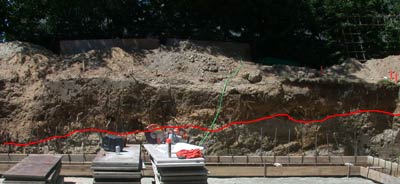
In spite of the house covering less than 1/3 of the lot, excavation ends up impacting the entire lot. The hole has to be ballpark three feet wider than the foundation to allow workers enough room to build the foundation walls, and then the dirt that will eventually be backfilled into the hole is piled up next to it, which itself takes up a lot of room. Because the old house was on a partial crawlspace, a lot of dirt had to be removed as well (it all went to fill in an old quarry). We did salvage as many plants as we could, although luckily there weren't that many of them.
Excavation did show us what kind of soil we have and somewhat explained the seasonal seep on the south (downhill) side of the lot. The red line in the photo above is an approximate dividing line between the good soil (good meaning is has a good mix of sand, organic matter and inorganic minerals as clay or silt) and hardpan, which has a very high percentage of clay. The good soil is very fluffy and grows things well, the clay is so hard that even the big excavating machine has to pound at it to dig it up. Our guess is that all winter long ground water runs on this layer of clay, and that for whatever reason restricts itself to 100' or so wide strip: our guess is that there was a seasonal creek drainage there long before development, and hence its still there.
In addition to digging out the crawl space to expand it to a basement, we also cut a slot for a driveway, and a hole for the rainwater tank. In addition we had the excavator take away any unneeded backfill soil that wasn't good enough, so that when we were done the ground level was actually lower than when we started allowing room to add good soil.
Rainwater
The rainwater tank was a bit of an experiment, and admittedly an expensive one. Although Seattle is a rainy climate, summers are usually very dry and so summer water is limited by reservoir capacity and snowpack (the later of which seems to be getting smaller), yet the maximum demand for water is in the summer. Our rainwater tank allows us to water most of the summer without having to use city water (the tradeoff is that its using a pump. Although most city water is pumped to create enough pressure, most of Seattle's water is gravity fed.) In order to make the tank useful the rest of the year, we also made the toilets flush with rainwater. The later was an interesting process since the city had no code at the time to allow this, and it took quite a bit of hassling to get them to allow it.
In reviewing various options, we decided on a cast in place concrete tank, and this choice was largely dictated by need to have the tank underground and the size of the tank. Our calculation were that we would need at least 5000 gallons of storage to get thru the summer, and that number turned out to be small, so even with the rainwater tank we end up using city water for the landscape and the toilets flush on city water all summer. We looked at three options: pre-cast septic tanks, polyethylene tanks suitable for burial, and the cast in place tank. Pre-cast tanks ran about 60 cents a gallon and come in various sizes, but typically around 1500 gallons. Above ground polyethylene tanks are somewhat cheaper, but the ones you can bury ran at least $1/gal and had a max size of 1750 gallons. The concrete contractor could do cast in place more or less any size we wanted for also about 60 cents/gallon, and we'd get a patio for free out of the deal, so clearly for us this was the best option.
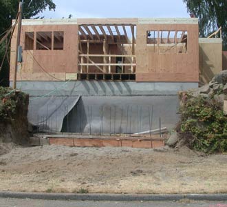
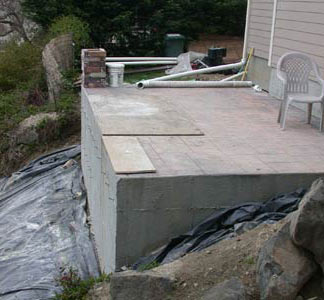
The tank is 10x16 and 6'6" inside, so its a big hole (left). Finished tank with patio on top (right).
Our system of collecting water from the gutters is very simple, but probably not as effective as the more sophisticated mechanisms. We installed a triangular grate covered with window screen. Compared to fancy commercial filters, this one costs less than $20 each. Its not that dusty here, so the main thing we want to filter out is leaf debris, so we simply put screen filters on each downspout. It means that when the flow down the downspout is very small, most of the water flows down the screen (due to surface tension) rather than in the tank, but it hasn't been a problem (you can see the sheet of water that has formed on the screen in the photo). The screens keep out the large debris fairly effectively, and admitted the tank hasn't been cleaned in many years, so its not clear how much sediment has accumulated: at least not so much that its obvious when you look in the tank at any point.
We ended up with two inlet ports in the tank, and two outlet ports. The two inlets are for the lines on the two sides of the tank. One outlet goes to the pump and the other is the overflow drain which is located high in the tank (but lower than the input lines so the water doesn't back up them, so when full the water is about 6" below the top) We considered having the overflow go into a rain garden, where any excess would run off into the street, but given the obvious soil conditions and the fact that our lot already seeped a lot of water all winter (ie the sidewallk is soaked most of the winter), there seemed to be no point in doing this, so the overflow went straight into the sewer (alas our neighborhood has the old combined sewer/storm drains). The rainwater tank buffers this a bit, but its generally full by Dec 31st, if not earlier, so the rest of the winter the 10-15 gal/day we use to flush toilets probably has little impact on how much ends up in the sewer. The tank also has a 24x24" access hatch which is located on the southern end of the tank. This location was done to keep the hatch out of the path across the tank, but since we sloped the tank to the south (away from the house), its also a low point, and while you might think concrete doesn't sag, it turns out it does, so the area around the hatch is now the place all the debris runs to when it rains. In retrospect it would have been better near a corner, where the concrete would be more like to stay flat...or at least anywhere but near the low point! The hatch its just a piece of 1/4" diamond plate steel painted with two coats of rustoleum hammered paint (ie very toxic, but very very durable!) set into the concrete. Mike of Living Systems Design designed a raised hatch that would eliminate most debris going in, but cost and laziness means it never happend.
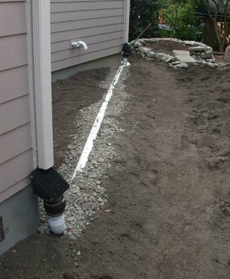
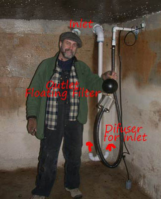
Gutter filters and drain connection to tank (left). This one is a little high because its the longest run, so the slope of the line forces the end up higher. Inside the tank (right). Water comes from gutters into the big pipe, and it directed upward near the bottom in an attempt not to stir up any silt that's down there. The tank outlet has a floating filter (the ball in Mike's hand is the float) which screens out any floating debris.
Our system went thru two iterations. The first one the plumber designed with our input, which worked bur proved to be unreliable (the motor would burn out but we had no idea why). The second system was designed by Living systems design (Mike in the photo above) has been completely reliable. The obvious lesson is that having done it before obviously helps. We changed from a fixed speed pump to a variable speed pump (they're 3x the cost), and changed the fixed intake to a floating intake as well as adding the diffuser pipes to the tank inlet lines. Other than that the system didn't really change.
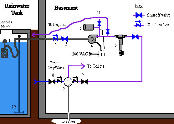
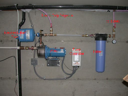
A schematic of our current system is shown above. The intake for the pump is a floating screen filter (1) which sits below any floating debris, but well above any that sink to the bottom. This is fed thru a 1" CPVC pipe to a check valve (2) (which apparently is to help the pump keep its prime) and a shutoff value (3) that has no obvious purpose A variable speed motor (4) keeps the output line to whatever pressure is set by the motor controller (10). The motor is a 240V unit which requires it's own circuit. The motor controller has an external pressure sensor in the output line (indicated by the thin black line). A small pressure relief tank (6) helps keep the system pressure stable when the pump starts up and shuts off. Connected to that same line is a valve & treaded (hose threads) input (11) that serves as a way to prime the pump. The pump output has two other tee connections: the first goes directly to the irrigation controller (for more on this see below), and the other goes to the filter (5), that removes most of coarse suspended solids so that the water in the toilets is mostly clear (the filter potentially keep the toilet valves from collecting crud--I don't really know if this is an issue of not).
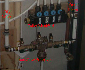
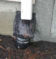
The output to the toilets is joined to a line from city water by a reduced pressure backflow protector (9), which is a device made of of check valves. A close-up of this is in the photo at right: city water comes in via the white pipe on the right, then thru the backflow protector and into the toilet manifold where there is a "T" with the purple pipe leading from the rainwater pump. The line dropping out of the backflow protector is and overflow which goes to a drain, and collects the excess when the backflow protector stops a reverse flow.
As a backup to this device, which apparently fail more often than you'd like, we put shutoff values on both side of the backflow device (7 & 8 but off the top of the close-up photo). The way we change over from one water source to the other is to always shut both valves off before turning the opposite one on. This way we're not really relying on the backflow protector for anything, other than a mistake in having both shutoff valves open at once. There is a redundant shutoff valve on the toilet side of the filter (5): this is just for convenience in doing repairs--it allows the filter to be removed. The blue line labeled "city water" looks like it comes in from near the tank but in reality its not connected to the tank in any way and comes in the house in a different location. All the rainwater plumbing lines are done with purple pipe (and drawn as purple lines in the diagram) as this is the code for non-potable water.
Landscape
Landscaping started by tilling up the existing soil (although avoiding big tree roots) and then adding 45 yards of garden mix and 25 more yards of compost, which gave us anywhere between 6-18" of good soil over the entire lot. From there the next step was hardscaping: creating paths, patios and sitting areas. In this step, we started with the rainwater tank, which had its surface colored and stamped to function as a patio. Rather than drawing a formal plan, we just walked around the lot with a few ideas in mind as much of the lot was heavily constrained by size and orientation. We wanted a private sunny patio, and since the SW corner was a low point, we built it there rather than on the rainwater tank. In the NW corner, we built a little serenity garden: a private space with a bench and a narrow entry where you can sit and feel in nature about as much as is possible on a small lot.
With those general goals in mind, and additional landscape goals of making the surface as permeable as possible (to minimize rainwater runoff), and to plant plants in their correct microclimate, the final layout is shown in the diagram above. The dark green lines indicates the approximate extent of the three trees that affect the yard: a large white pine in the SE corner, a large birch (which is now larger than shown) in the NE corner, and another birch in the neighbors yard on the west. The shading of green is an approximation for how much sun the area gets: lighter is more sun, darker less.
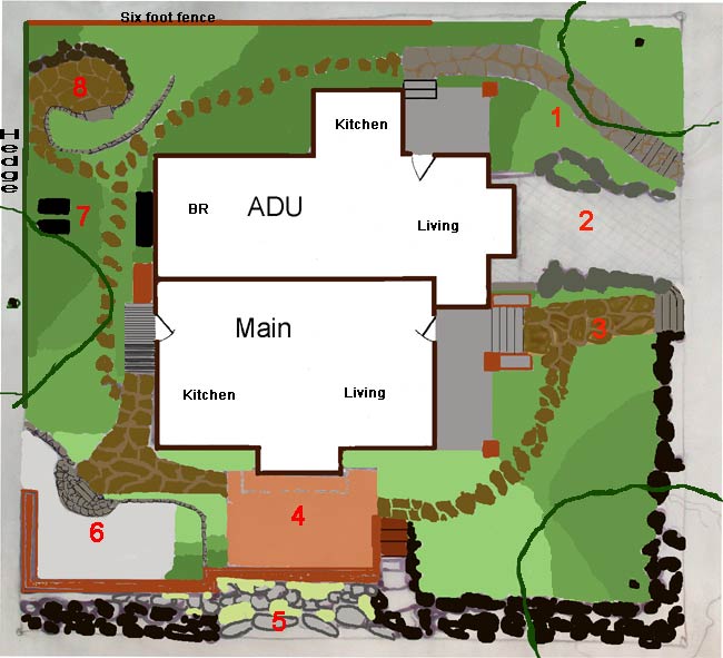
The above diagram shows how the landscape is broken up into "rooms", where each numbered area has a unique characteristic, which are as follows:
- This walkway is broken concrete salvaged from our site. The front porch is a 3" concrete slab with a Trex railing. This area is the front yard for the ADU and is fairly well separated from the main house yard by the recessed driveway.
- The driveway is Ecostone pervious pavers, with a drain at the bottom.
- This walkway and most of the others are slate (from Montana). The porch is concrete with a Trex rail.
- The top of our rainwater tank is also a patio, which is the warmest place on our lot. It is our only completely non-pervious surface.
- The south side brick wall is reclaimed brick from the old house, the area below is granite boulders which hold a hot, dry landscape. This brick wall is actually double with about 8" of space in between the wall which is a planting box used to grow annual flowers or vegetables. On the east side of the rainwater tank, there is a stairway, we call the "goat path", carved out of rocks and old bricks. The vertical drop down to the sidewalk here is between eight and ten feet.
- This area is a summer patio because its not as hot at the rainwater patio. It is surrounded by a rubble concrete wall, that was salvaged from nearby places in Seattle (via craigslist).
- Here are our compost bin, our shed for the "brown" material needed to mix with food waste, and a place to store our yard waste bins.
- This is our serenity garden. Its the quietest, most private place on our lot.
While the intent had been to use only drought tolerant plants, the garden evolved to having a wide diversity of plants so that something would bloom (or have interest) all year long. At one point there were over 350 species, although the number is now much reduced to probably closer to 250, which is still a large number. At each planting, we dig the hole a bit too deep, trying to get to the original soil layer, then mix the two soils together before planting, so at each plant site the depth of good soil is extended to at least a foot deep and in many places much deeper.
While many of the plants are at least somewhat drought tolerant, many are also not, and of the ones that are somewhat tolerant, many look much better with some water. One of the difficulties in having a lot of variety is that the two birch trees are huge water suckers, and then you add the large white pine and the lelandi cypress hedge, and the water demand from those large plants alone is quite large. Because most truly drought tolerant plants are sun loving, and the lot is largely shaded, to be truly drought tolerant would require plants that will take dry shade, and alas the variety available there is not large. That said, gardening is very complex, and an interesting garden also takes a lot of work, which is something we no longer want to do, so the garden, while still very nice is just less complex (and hence less interesting) than it once was.
Our entire yard is divided into 4 watering zones: the south side where the true drought tolerant plants are gets no water other than an occasional dump of a watering can. The other four zones theoretically would get differing amounts of water, but due to the trees, they're currently getting the same amount. We have a 6 zone drip irrigation controller which is fed solely by rainwater and we use only 3 zones. As the garden matured we've discovered the limitation to drip irrigation--its great for small plants by really lousy for bigger ones. The main problem is that the water doesn't spread over a wide enough area in the root zone unless you use the sprayer type heads instead of the actually drippers which result in 4-6" diameter wet spot that doesn't seem to spread much.
Inside Water Use
When we built in 2004, most faucets and shower-heads were already "low flow", so our take was that the bigger issue was how well you could control the flow and for showers, did water coming out feel sufficient to do the job. We used mainstream mid-line plumbing fixtures, and made sure the shower had a volume control as well as temperature, so that we could reduce the flow if we wanted, and as it turned out, we typically run it at about 2/3 full force, which we guess is more like 1.5gpm (versus the max rated 2.2gpm., and sometimes we turn it lower.)
Our plumbing system is PEX in a home run configuration, which means each fixture has it own pipe, just like how each electrical circuit is one wire run. All the pipes then run into a manifold. The advantage of this over the normal plumbing setup, at least from a single fixture point of view, is that the pipes are much smaller (since they serve only one fixture) and hence whether your waiting for hot or cold water to come out, it comes out a lot faster. How much water this saves is unclear, but it sure produces hot water in the shower quite fast (for a detailed discussion on the topic, see the hot water section).
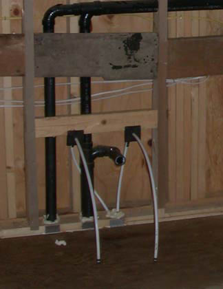
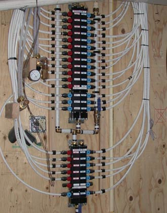
PEX home-run system: each fixture gets it own lines as can be seen in the sink connection (left). In the basement, each line has its own shutoff (blue & red circles). In retrospect, we should have put angle stops in at each fixture as well because it would make repairs much eaiser.
While 1.6gal/flush toilets were the only thing available at that time (the others having been recently banned), there was a big difference in how effective the various models were: the best models got rid of everything on the first flush, the worst didn't. We went with the Toto Drake, which at the time was one of the top five most effective (according to the testing done by the savingwater.org alliance). While we've been very happy with it, there are now many models that flush at 1.28gal/flush and some that use even less water.
The final step was appliances. The main unit has a very efficient dishwasher (Asko) and a reasonably efficient washing machine (Fisher Paykel), but the apartment has just mainstream appliances due to cost reasons.
While not really a directly a water issue, we rebuild the sewer line because the original one came out of the street too high to have basement drains. We could have gone with the tank/pump system, which is the lower cost standard solution, but given that pumps inevitably fail, we went with the more durable solution and rebuilt the line so that gravity would be able to drain the whole house.
The only final miscellaneous topic has to do with plumbing vents: mostly that there end up being far too many of them, and they end up in exterior walls, which means both extra places for air leakage and empty space that could be insulation. The pluming code apparently requires the vent to have the same cross-sectional area as the drain and does allow for them to combined sometimes, but for whatever reason there didn't seem to be much combining.